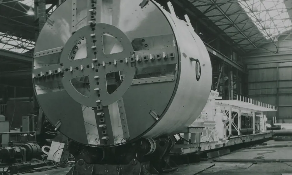
Tunnelling over time
Boring tunnels through soft rock (such as the chalk on the English side of the Channel Tunnel) or through cohesive soil (such as the London Clay that most of the capital’s tube system goes through) is a comparatively straightforward affair. But non-cohesive soils – sands, silts, gravels and mixed ground, where the tunnel face requires continuous support and where ground water almost always threatens to flood the works – present an altogether greater challenge. Traditional solutions include working under compressed air, which is extremely hazardous, and more recently, ground freezing or chemical treatment, which can be very expensive. This explains why deep tunnels were not feasible beneath many of the world’s cities, and why London’s tube network excluded the southeast of the city where suitable clays were not available, until the Jubilee line extension was constructed in the mid-1990s.
non-cohesive soils – sands, silts, gravels and mixed ground, where the tunnel face requires continuous support and where ground water almost always threatens to flood the works – present an altogether greater challenge
John Bartlett CBE FREng’s idea for a radical solution came after a visit to Milan in 1963 to advise a contractor on tunnelling through the city’s gravel deposits, laboriously using traditional methods. While there, he was able to observe how Milan’s first metro line had been built, using ‘cut and cover’ rather than bored tunnels. Italian engineers had developed diaphragm walls, an ingenious method of constructing vertical retaining walls in non-cohesive ground by exploiting the properties of bentonite clay to support trenches during excavation. Bentonite is a commonly available clay material that, when activated by chemical treatment to form a slurry, becomes thixotropic (a gel when at rest but a liquid when agitated or in motion). On his flight back to London, Bartlett visualised how slurry trenches and mechanical digger technologies could be combined to create a new type of tunnelling machine, with fluid support of the working face.
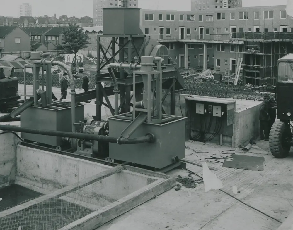
The spoil/slurry treatment plant at the head of the shaft for the New Cross experimental tunnel in 1972, showing twin 12-inch diameter hydrocyclone units and a vibrating screen behind © Institution of Civil Engineers
The essence of the invention is the use of a thixotropic slurry such as bentonite that is under pressure in a sealed bulkhead at the front of the tunnelling machine, so that the tunnellers behind can work in air at normal pressure
The outcome was Bartlett’s bentonite tunnelling machine, which he patented in 1964. The essence of the invention is the use of a thixotropic slurry such as bentonite that is under pressure in a sealed bulkhead at the front of the tunnelling machine, so that the tunnellers behind can work in air at normal pressure. The pressurised bentonite slurry balances the water pressure in the ground, thereby preventing it from flowing into the tunnel and causing major instability. In larger-grained soils, such as coarse sands and gravels, the bentonite also penetrates the ground for a short distance ahead of the excavated face, providing additional stability. The pressurised bulkhead in the tunnelling machine contains a mixture of the bentonite slurry and the excavated soil, which has been cut by the rotary wheel at the front of the closed-face machine. A unique part of the invention is the use of the slurry itself to transport the excavated soil from the pressurised bulkhead via a pipework system to separation tanks on the ground surface. The excavated soil is then separated from the slurry, which is then recirculated through pipework back to the pressurised bulkhead.
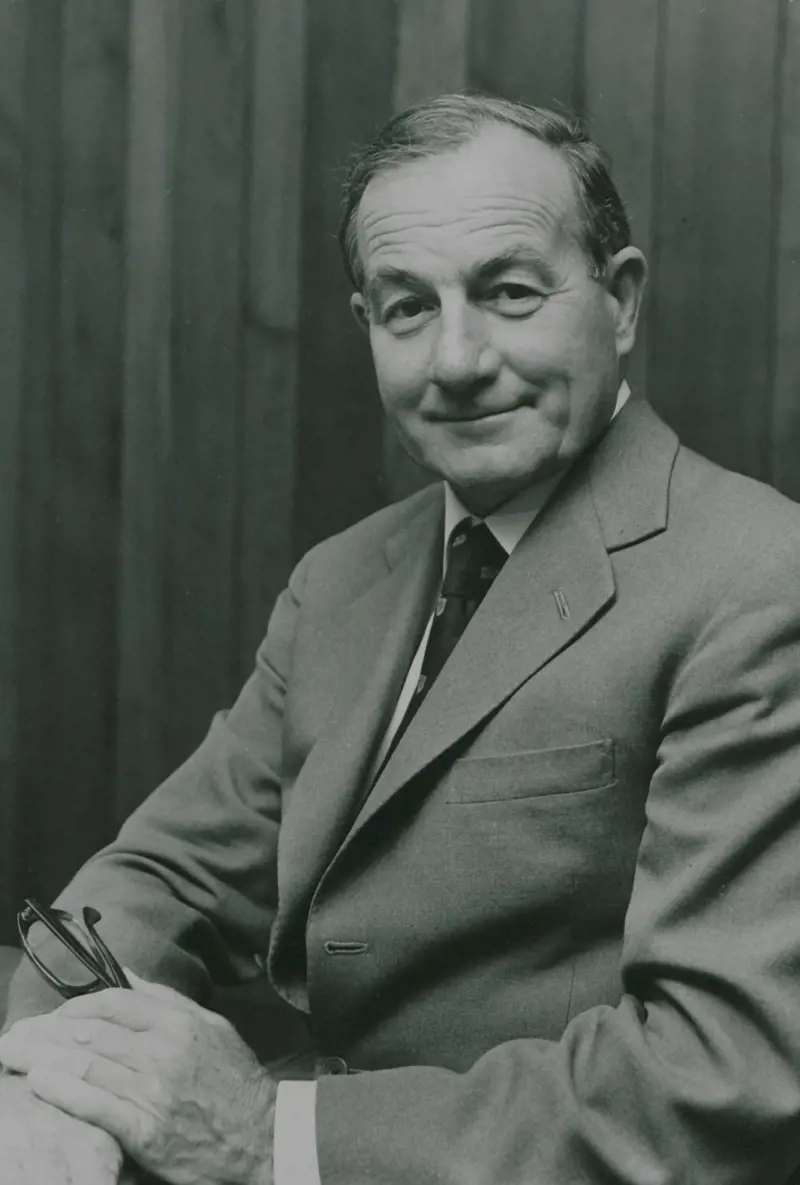
John Bartlett CBE FREng
🚆 John Bartlett CBE FREng's career and famous projects
John Bartlett CBE FREng spent most of his career with consulting engineers Mott Hay & Anderson (MH&A), from 1957 until his retirement as chairman and senior partner in 1988. In his early years, he worked on the first Dartford Tunnel, the first tunnelled sections of the Toronto Subway and improvements to the Blackwall Tunnel. He was the project engineer responsible for London’s Victoria Line.
From 1966, he was the partner and director responsible for the firm’s transport and tunnelling work, including further projects in London and Toronto, advisory appointments in Madrid, Brussels and elsewhere, and design and construction of the second Dartford Tunnel and the Melbourne Underground Rail Loop. He headed the project management of the Tyne and Wear Metro, coordinating its design and construction.
He also had design responsibility for the Channel Tunnel, first as principal designer for the scheme that was started in the early 1970s but abandoned by the UK government in 1975; and again with the revised scheme when MH&A was appointed by the Anglo-French consortium Trans Manche Link as the principal design consultant for all civil and geotechnical engineering on the UK section.
He took out his patent for the bentonite tunnelling machine (BTM) in 1964, and designed and supervised construction of the first, experimental, BTM tunnelling contract in southeast London in 1971–72. In 1973, he was awarded the Royal Society’s SG Brown Medal for the invention of the BTM.
He was a founder member of the British Tunnelling Society and its chair between 1977 and 1979. In 1978, he was elected as a Fellow of the Royal Academy of Engineering, and was President of the Institution of Civil Engineers in 1982.
In 1988, he retired as chair of MH&A, having overseen the firm’s transformation from a small London consultancy to worldwide success with major projects in five continents, and having led the merger talks that to the formation of Mott MacDonald in 1989, now one of Britain’s leading firms of consulting engineers.
Global use
It took many years to find the funding to take the invention forward, but in 1971 a prototype machine was built to drive an experimental section of tunnel in New Cross, southeast London, for London Transport who were planning to extend the tube network. The experiment was deemed to be a great success, with tunnelling rates of four metres per 10-hour shift achieved. The invention, and the prototype, included all of the essential ingredients of all the many slurry tunnelling machines (STMs) that were to follow all over the world, although many improvements were made on the way. Unfortunately, further development happened outside the UK, since – apart from a single sewer contract in Warrington – no suitable projects emerged in Britain for a decade or more.
One of the visitors to the New Cross experiment was Eric Jacob of Frankfurt-based firm Wayss & Freytag AG who developed the Hydroshield, very similar to Bartlett’s machine but with some important improvements – particularly the introduction of an ‘air accumulator’ to maintain a constant fluid pressure at the tunnel face. This was first used on a sewer tunnel in Hamburg in 1974, and later on projects such as the Antwerp and Lyon metros. However, most of the subsequent development work occurred in Japan, fed by a major demand for tunnels in non-cohesive ground. Initially these Japanese developments produced improved STMs, all derived from the principles of Bartlett’s bentonite machine. By the end of the 1970s, more than 1,000 STMs had been used worldwide.
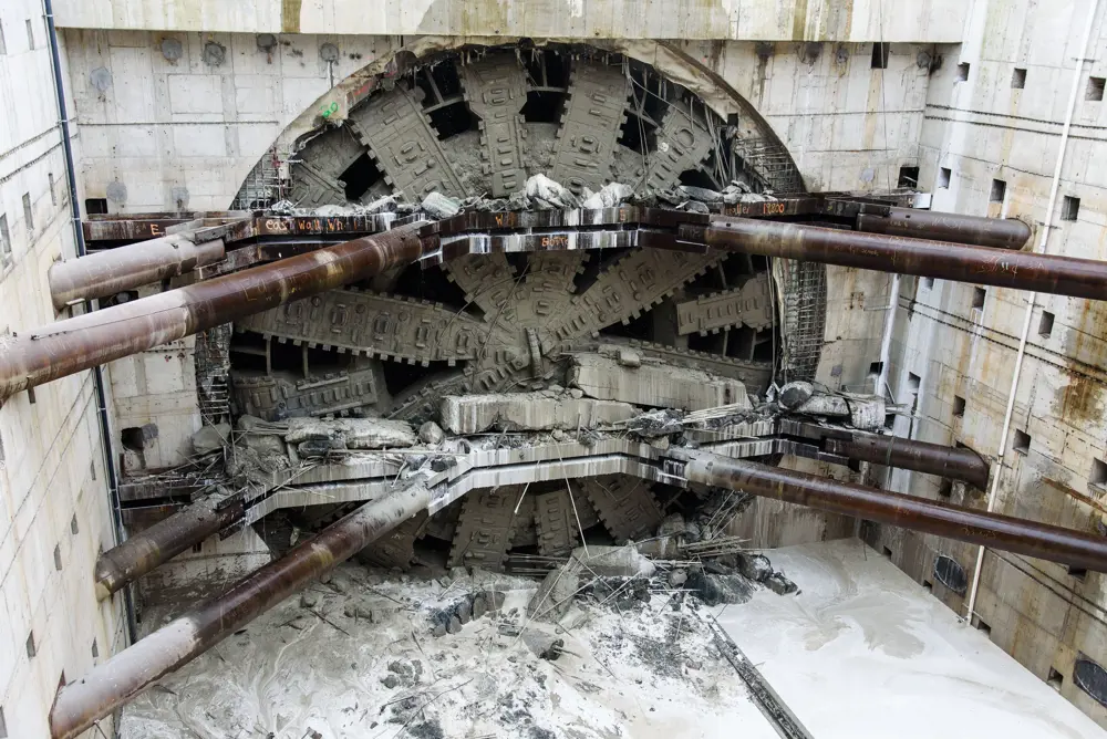
Bertha’s breakthrough at the end of the two- mile drive for the Alaskan Way tunnel © Washington State Department of Transportation
Meanwhile, an important Japanese innovation led to the earth pressure balance machine (EPBM). This uses the same principles of ground support as the Bartlett invention but with the face supported by conditioned excavated spoil rather than a slurry, and with the excavated spoil removed from the face using a screw conveyor. The EPBMs were being used extensively in Japan from the late 1970s. Almost all subsequent tunnelling machines for non-cohesive ground can be classified as either EPBMs or STMs: the former tend to be used in silty, clayey soils, with STMs preferred in more granular soils.
In the 1980s and 1990s, major projects that used STMs included the British-financed Cairo Wastewater Project, Tokyo Bay road tunnel and the Elbe road tunnel in Germany, while five EPBMs were used for the difficult ground on the French side of the Channel Tunnel, two for Toronto Metro, four for the Storebaelt rail tunnel in Denmark, and one for the St Clair River rail tunnel on the US/Canada border. The Channel Tunnel Rail Link used three EPBMs and one STM.
In the new century, STMs have been used (for example) for the Groene Hart rail tunnel in Holland, the British-designed SMART tunnel in Kuala Lumpur, the Chong Ming road tunnel in Shanghai, the Hallandsås rail tunnel in Sweden, and the Bosporus Eurasia road tunnel in Istanbul. EPBMs have been used in the development of a water tunnel in Buenos Aires, San Diego Outfall tunnel, A86 a L’Ouest de Paris, Westerschelde road crossing in the Netherlands, Tokyo Metro, Moscow Silbenwald road tunnel, M30 Madrid road tunnel, Sparvo road tunnel in Italy and Copenhagen Metro. In the UK, numerous EPBMs were used on Crossrail, while STMs were chosen for the Lee Tunnel, the first section of London’s Thames Tideway ‘super sewer’ project.
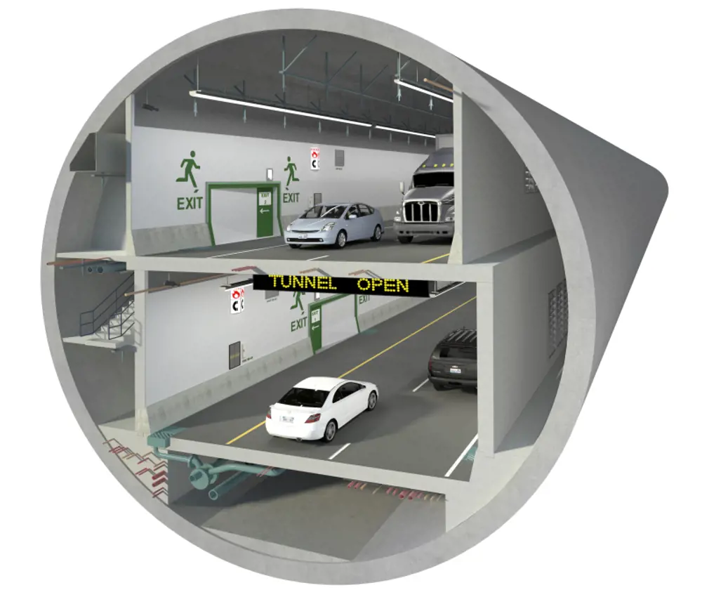
A computer-generated image depicts a cross-section of the Alaskan Way tunnel, showing four lanes of highway with with two at the top and two at the bottom © Washington State Department of Transportation
Scaling the machines
Many of these machines have been in the 11 metre to 15.5 metre diameter range, the largest being 15.55 metres, but two tunnels have recently been driven with diameters of more than 17 metres. ‘Bertha’, the machine for the Alaskan Way highway tunnel in Seattle is the world’s largest EPBM (17.48 metres) while the Chek Lap Kok road tunnel in Hong Kong is the world’s largest STM (17.63 metres).
Such huge diameters bring issues of scale. Taking the example of Bertha, at the simplest level, the machine’s height is more than a five-storey building so just getting from the bottom to the top is a major climb for the tunnellers. At any time, the machine may be straddling several different geological layers, and the weight of the cutterhead and drive unit is nearly 2,000 tonnes. A ring of the permanent tunnel lining comprises 10 segments, each of which weighs up to 16 tonnes and has to be placed behind the machine using vacuum lifting. The maximum thrust to drive the machine forward is 39,000 tonnes, and the total power is 13.44 megawatts.
The Alaskan Way tunnel is two miles long through difficult, seismic ground, and will replace an elevated two-level highway along the Seattle waterfront. It will carry four lanes of highway, stacked with two at the top and two below. The tunnel broke through in April 2017, the internal roadways are complete, and final testing is underway before opening.
Tuen Mun-Chek Lap Kok Link
Meanwhile on the other side of the Pacific Ocean, one of the world’s most ambitious construction projects is slowly taking shape – the Hong Kong-Zhuhai-Macau Bridge, with three cable-stayed bridges, three artificial islands and an underground section carrying a new 50-kilometre-long road eastwards from Macau, through the Chinese prefecture of Zhuhai to Hong Kong where it will terminate by Hong Kong’s Chek Lap Kok airport on the western island of Lantau.
From there, a new four-kilometre-long undersea tunnel is being driven to connect to the mainland at Tuen Mun in western Hong Kong. Hong Kong has a long tradition of crossing its sea channels with immersed tube tunnels, comprising prefabricated concrete sections floated out and sunk in a dredged channel to form the tunnel.
However, in this case, this would have involved major dredging across a busy shipping channel – and across the ‘dolphin corridor’ used by endangered pink dolphins. Instead, it was decided to bore twin tunnels 50 to 60 metres beneath the seabed, mainly through alluvial clays with frequent sand lenses, with some weak rock (decomposed granite) and mixed ground. Each tunnel contains two lanes of traffic. But for the steep, 680-metre-long exit at the Tuen Mun end, the northbound carriageway widens to three lanes, which is where engineers needed the large STM.
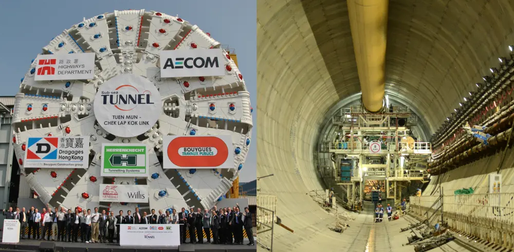
Left: The world’s largest ever tunnel boring machine, the 17.6-metre-diameter slurry tunnelling machine prior to its use to drive a part of the Chep Lak Kok to Tuen Mun subsea tunnel in Hong Kong; right: The smaller 14-metre-diameter tunnel boring machine driving one of the twin tunnels for the Hong Kong tunnel
After successfully completing its 680-metre-long drive, the 17.6 metre STM was converted to a 14-metre diameter machine for the remainder of the drive, by changing the cutterhead and shield but retaining the remainder. A second 14-metre diameter machine was brought in for the other carriageway.
A persisting challenge with STMs is abrasion on the cutter discs at the front of the cutterhead, which require periodical replacement when worn-out. ‘Mobydic’ – a system of sensors incorporated into the cutter discs to enable wear to be monitored as well as providing real-time geological monitoring – was successfully used on both tunnels, while two other innovations – ‘Snake’, which is a remote control mechanical arm for cleaning the cutterhead, and ‘Telemach, an automated disc-cutter replacement mechanism – were also introduced. Even so, specially trained workers often needed to enter the chamber to replace discs. Where possible, this was done in ‘saturation mode’, which allowed longer daily working times of up to six hours and greatly reduced the frequency of compression and decompression, thereby reducing the risk of ‘decompression sickness’ among the workers.
Starting a revolution
“There can be no doubt that a major revolution in the worldwide tunnelling industry was triggered by John Bartlett’s invention of the closed face bentonite tunnelling machine,” says Lord Robert Mair CBE FREng FRS, President of the Institution of Civil Engineers. “The invention allowed tunnels to be constructed in hitherto difficult and hazardous soil conditions with complete safety and without risk to the operatives. This has enabled a very rapid increase in tunnel construction around the world, particularly in urban areas, for water supply, sanitation and transport – with remarkable benefit to humanity. It has consequently resulted in hugely improved infrastructure in many of the world’s cities, especially in developing countries, which is of considerable importance in view of the rapidly increasing urbanisation across the world.”
***
Since this article was published, the Alaskan Way tunnel was opened in February 2019 and the Hong Kong-Zhuhai-Macau Bridge was opened in October 2018.
This article has been adapted from "Tunnelling over time", which originally appeared in the print edition of Ingenia 76 (September 2018).
Contributors
Hugh Ferguson
Author
Keep up-to-date with Ingenia for free
SubscribeRelated content
Civil & structural

Building the Shard
The Shard is one of London's most iconic buildings. The tallest in Western Europe, it was designed by Italian architect Renzo Piano and dominates the city’s skyline. Ingenia spoke to John Parker, project director for structural engineers WSP, who outlined the engineering decisions made in building the enormous steel and glass structure.

The return of arched bridges
Arch bridges are strong, durable and require little maintenance. However, very few had been built since the early 1900s until the FlexiArch was developed and launched in 2007. Now, there has been a minor renaissance for this ancient form of construction.

Creating user-friendly buildings
For Michelle McDowell, a former Business Woman of the Year, a passion for joined-up design thinking and building information modelling with a user-friendly approach has enabled her to pioneer revolutionary changes in her field.

Troja Bridge
In November 2014, one of the world’s largest network arch bridges was officially opened in Prague. The UK may soon have its first network arch bridge if the go-ahead is given for a new rail project in Manchester.
Other content from Ingenia
Quick read

- Environment & sustainability
- Opinion
A young engineer’s perspective on the good, the bad and the ugly of COP27
- Environment & sustainability
- Issue 95
How do we pay for net zero technologies?
Quick read

- Transport
- Mechanical
- How I got here
Electrifying trains and STEMAZING outreach

- Civil & structural
- Environment & sustainability
- Issue 95