
Beamforming
Broadly, today’s 4G technology could be likened to having a lightbulb illuminating a whole room (or in some cases one-third of a room in a pie-shaped ‘sector’). Tomorrow’s 5G technology will focus the radio energy towards the handset in a narrow beam more like a searchlight.
This has two key advantages. First, focusing the energy means that it goes further, much as a torch can cast a beam further than a lamp, enabling greater range from base stations. Second, if there are multiple beams formed within a cell, and if these are not overlapping, then the same radio frequencies can be used for each beam, but with each one sending different information pertinent to their subscriber (the person using the device). The number of beams then increases the capacity of the cell.
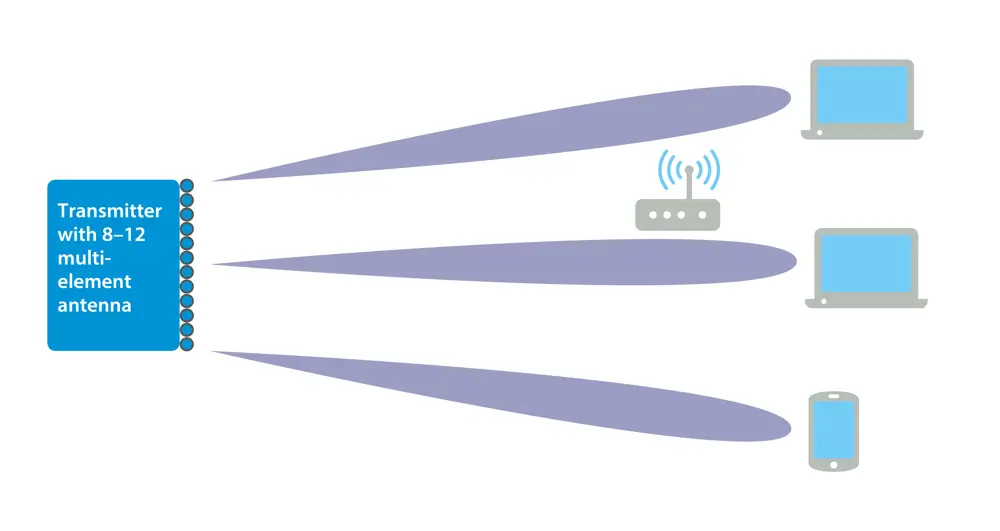
This diagram demonstrates how narrow beams can send different information to multiple subscribers
Beamforming antennas do not use a lens as these are both difficult to make for radio systems and hard to steer mechanically towards the subscriber. Instead, they make use of a large number of elements, or mini antennas, within a larger structure. Antennas proposed for 5G base stations have 64 or 128 small antennas within them. A beam is then formed by taking several of these elements for one subscriber (say four or eight) and sending the same signal to each element but delaying the signal to some of the elements. This has the effect of steering the beam as shown right.
These ideas of forming beams by phasing signals to discrete antennas are far from new: radar and sonar systems have used them for years. However, this will be the first time that they will be applied to mass-market cellular systems.
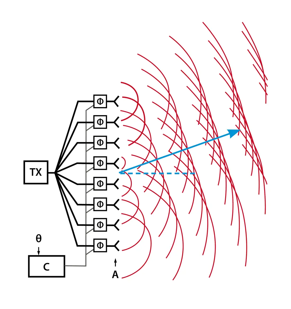
Changing the phase of the signal causes a beam to be formed in a particular direction
To understand intuitively how the beam is steered, think of each antenna as transmitting a wave of radio energy. At the receiver, all these waves add up together in the antenna. If just two antennas were used, in some places their signal would be in phase so that the peaks in the wave arrived simultaneously. Here the receiver would see a strong signal. At other places, they would be precisely out of phase so that the peak of one wave arrived along with the trough of the other. Here the signals would cancel and the receiver would see nothing. A receiver that was not directly perpendicular to the antenna would be further from one antenna than the other, so by delaying the signal to the closest antenna by the time that corresponds to this distance then a strong signal will be received. Two antennas would give rise to a whole series of these strong and weak areas. However, as more antennas are used the number of these areas reduces, resulting in a progressively narrower beam, which forms alongside the main beam as a function of the number of signals combined and their relative delays.
A different subscriber is then assigned another set of elements where different delays are used to steer that beam in a different direction.
There are many trade-offs. The more elements used per subscriber, the more focused the beam is and less focused the unwanted ‘mini-beams’ created around the main beam. However, where there are more elements, the larger and more expensive the base station antenna becomes. Also, as the beam becomes narrower, it becomes harder to keep it perfectly aligned on the subscriber, especially if they are fast moving.
These ideas of forming beams by phasing signals to discrete antennas are far from new: radar and sonar systems have used them for years. However, this will be the first time that they will be applied to mass-market cellular systems.
***
This article has been adapted from "How does that work? Beamforming", which originally appeared in the print edition of Ingenia 78 (March 2019).
Keep up-to-date with Ingenia for free
SubscribeRelated content
Electricals & electronics

Accelerometers
Used in earthquake measurements, laptops, planes and even in stargazing apps, today’s accelerometers are much smaller than when they were first developed in 1927. Find out how they detect movement and vibration.

How to maximise loudspeaker quality
Ingenia asked Dr Jack Oclee-Brown, Head of Acoustics at KEF Audio, to outline the considerations that audio engineers need to make when developing high-quality speakers.

Cable fault locator
The winner of the Institute of Engineering and Technology’s 2014 Innovation Award was EA Technology’s CableSnifferTM, which uses a probe and chemical sensing technology to identify faults, saving energy companies millions of pounds each year.

High speed evolution
In December 2010, Eurostar International Ltd awarded a contract for 10 new high speed trains to Siemens. The company has used a system developed over decades to maximise the performance and passenger-carrying ability of its 320km/h trains.
Other content from Ingenia
Quick read

- Environment & sustainability
- Opinion
A young engineer’s perspective on the good, the bad and the ugly of COP27

- Environment & sustainability
- Issue 95
How do we pay for net zero technologies?
Quick read

- Transport
- Mechanical
- How I got here
Electrifying trains and STEMAZING outreach

- Civil & structural
- Environment & sustainability
- Issue 95