A tower with a twist
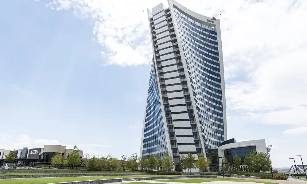
Developer Attacq and its development manager Atterbury wanted an iconic building as the centrepiece of a new city district some 25 kilometres north of central Johannesburg. The architect, LYT Architecture, proposed a 26-storey triangular building with three concave glass walls – twisting clockwise (looking from above) as it rises from the ground. The twist aims to create an organic form, with the building looking more like a sculpture than a rectilinear block and creating the illusion that the building is rotating as it extends from its hilltop perch.
The concept is simple to describe, and even to sketch, but at the same time it introduces all sorts of geometrical and analytical complications. This is not the first twisted building – it is believed to be the 26th tallest of one form or another in the world, although the first in Africa. Here, the engineering team had to address the challenges without adding to the cost of construction and without compromising the office floor plans in a way that made them less attractive to tenants. “An engineer” according to an old American adage “can do for a dollar what any fool can do for two”, and that was what the engineers had to do with the PwC Tower.
The biggest challenge was the spiralling form of the tower. A regular structural form that followed the twist of the building would create a clockwise torsional load because the building tries to fall in on itself
The biggest challenge was the spiralling form of the tower. A regular structural form that followed the twist of the building would create a clockwise torsional load because the building tries to fall in on itself. The traditional solution would have been to stiffen the cylindrical concrete tower that forms the central spine of the building, to resist the torsional load. Initial calculations showed that this would require a two-metre thick, heavily reinforced core wall. This would not have fitted in with the aesthetics of the tower, as well as taking up valuable space, and would have been far too expensive. Instead, the engineers proposed three alternative column arrangements that would reduce or counteract the torsion.
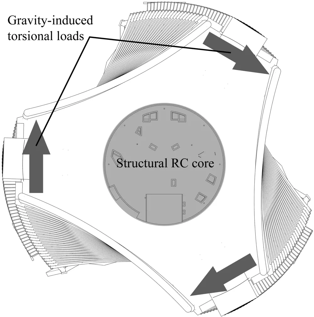
The spiral form of the triangular tower induces a clockwise torsional load on the concrete core © Arup
Handling the load
The first scheme was to avoid generating any torsion. If the twist was much smaller and the columns were all vertical, then varying lengths of cantilevered floors could make the building appear to twist while the structure did not. With greater twist, sloping columns could create the same effect, but ensure that all the structural columns slope away from or towards the centre of the building in a radial orientation. All lateral components of the axial forces in the columns therefore intersect in the centre of the building, while the structure, in effect, slopes away from or towards the centre, and consequently generates no torsion. Unfortunately, this idea resulted in an irregular pattern of columns that detracted from the building’s spiralling form and did not fit with the aesthetics of the design.
The second scheme kept the columns at the ends of the building, which twisted clockwise with the form, but arranged the internal columns in an anticlockwise spiral, circular in plan, and with a diameter just small enough to ensure that the columns were entirely within the building. By placing the columns at the right slope it was possible to perfectly balance the torsional load from the end columns to eliminate, or at least drastically reduce, the torsional load on the core. It was easy to assess the required slope as each column was equidistant from the centre, so the ‘lever arm’ was the same. However, this scheme played havoc with the space planning: internal columns appear in different places on each floor, interfering with the usable space and requiring a different strategy for planning space for each floor.
The challenge was how to optimise the complex structure and, more particularly, how to optimise the slope and spacing of the columns, for structural efficiency as well as for aesthetic effect and buildability
The third scheme was similar, but with the columns pushed out to the facade of the building. This approach freed up the interior for flexible space planning throughout the building, with almost identical floor plans on each floor, but it also introduced additional complexity. Columns are curved in three dimensions up the height of the building to match the facade. However, each column actually comprises straight floor-to-floor sections, with slight angles introduced at each floor, and so the sections vary in both slope and orientation to the core. The columns intersect the floors at different distances from the centre, creating different ‘lever arms’, and so each column exerts a different torsional load on the structure. The challenge was how to optimise the complex structure and, more particularly, how to optimise the slope and spacing of the columns, for structural efficiency as well as for aesthetic effect and buildability.
Parametric modelling
🏗️ Digitally evaluating an infinite number of design variations
Parametric modelling allows a digital model of the geometry of a building to be created and then manipulated using a series of pre-programmed rules or algorithms – the ‘parameters’. This enables engineers to evaluate the effects of changing some crucial elements of the design, quickly and simply.
For the PwC Tower, certain elements – such as the floor-to-ceiling height – were fixed. Then, the engineers created variable parameters within the model, including: the column slope; the column spacing; the number of storeys; the amount of twist per floor; the radius of the arc of the concave glass facades; and the number of facade panels across the width of each facade. For example, the slope of the columns could be changed by manipulating a ‘slider’ on the computer screen, the model would then adjust all other elements of the design to accommodate the change in slope, and the effect on the geometry of the building could be observed continuously on screen.
This helps the architects and engineers to judge what would, or would not, work aesthetically. The parametric model also provides input for more conventional software, including structural analysis software to calculate the stresses, and building information modelling (BIM) for communicating design information.
In this way, engineers can easily evaluate an infinite number of design variations, without having to go through the time-consuming process of re-inputting the data for each iteration.
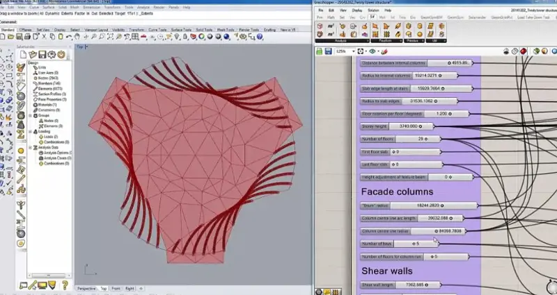
Parametric modelling is the modelling of a structure in n-dimensional space, where certain chosen parameters of the structure are variable. This allows the team to explore the impact of changing any of the input parameters on the design and cost of the structure, simply by moving a ‘slider’ on the screen © Arup
Modelling the twist
Manually setting up even one finite-element model would have been time-consuming: modifying the model to test many different slopes and column spacings would have been wholly impractical. The only feasible solution was to set up a finite-element model with varying parameters, and to choose the best model as the solution, which was less time consuming. Using parametric modelling software, the structural engineers modelled the tower’s geometry in great detail. This was done in such a way that certain variable input parameters determined the geometry of the structural analysis model in Arup’s well-established Oasys GSA analysis and design software, which calculated the stresses after the engineers had inputted the geometry and loads.
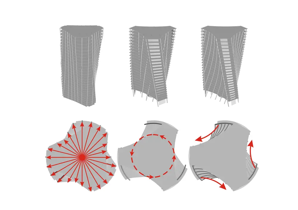
Plan and isometric sketch of each of the three alternative schemes for columns: (a) radially sloping columns; (b) internal spiral columns; (c) sloping facade columns © Arup
The variables could include not only the column slopes and spacing, but also the number of storeys, the amount of twist per floor, and the radius of the arc of the concave glass facades, among other factors. Setting up the parametric model was time consuming, but subsequent analysis was fast and provided a useful tool for interchanging ideas with the architect: the engineers could use a ‘slider’ to vary one parameter [see Parametric modelling], revealing the implications almost immediately. The model also proved useful for other aspects of the design.
Setting up the parametric model was time consuming, but subsequent analysis was fast and provided a useful tool for interchanging ideas with the architect
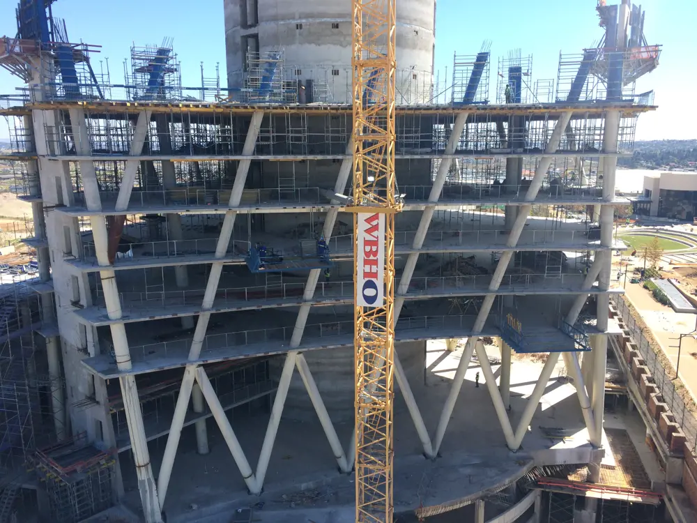
The chosen arrangement of columns under construction, with five across the width of the facade and repetition every five floors. Each column is spiral in shape, but made up of storey-height straight sections with changes of angle at each floor. The counter-sloping columns are purely architectural – to create a V pattern at the lobby level – and carry no loads © Arup
After many iterations, the chosen solution was five columns along the slab edge, and a ‘repeat’ of the column positions at the slab every five floors. This proved a satisfactory compromise between the various objectives. The configuration generated a torsion that countered 87% of the structure’s gravitational torsion: the core carried the rest, but the reduction in the proportion of torsion it had to carry allowed the core wall’s thickness to be reduced to just 450 millimetres – no larger than it would have been with no twist, and similar to many conventional buildings of similar height. The resulting column spacing of about eight metres matched the internal spans of the slabs and suited the basement parking layout. The arrangement also tied in with window mullions (the vertical bar between the panes of glass) and produced a form of symmetry that worked aesthetically and allowed considerable repetition for economy of construction.
Parametric modelling also helped optimise the design of the glass facades with their complex geometry: the short ends are both horizontal but not parallel and the edges are not necessarily at the same angle to the glass, while the long sides are not vertical or parallel in either frame. It would have been prohibitively expensive to produce glass curved in three dimensions to match the facade shape: instead the aim was to produce flat glass panels, and take out the curvature within the aluminium mullions (vertical) and transoms (horizontal) between the panels. It was decided to run the mullions parallel to the edges of the facades so that they were not actually vertical, with roughly constant spacing between mullions. The transoms were defined as horizontal at each floor level, and then the engineers used the model to test various mullion spacings to obtain a satisfactory compromise. The change of inclination at each panel had to be small enough both to maintain the illusion of continuously curving glass and to avoid excessively deep mullions.
The result was a series of storey-height (3.7 metres), prefabricated panels with flat glass but distorted mullion shapes to absorb the change of curvature: the panel widths are roughly 1.5 metres, but each varies slightly and is non-parallel.
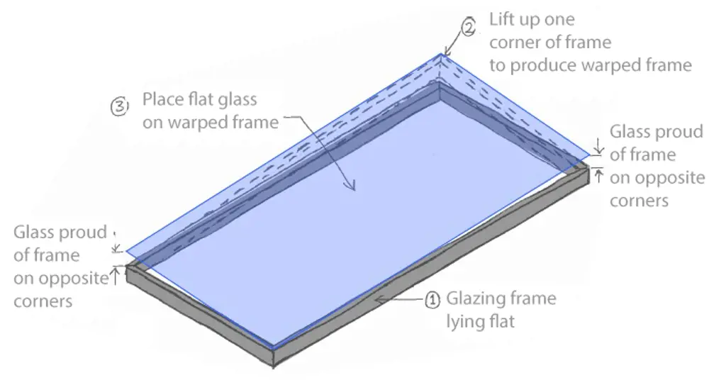
Each of the facade panels is warped to accommodate the twist, but a glazing sub-frame within the panel allows the glass to be flat and sit in one plane. All of the geometrical abnormalities were cleverly hidden within the depth of the frame © Arup
Tackling 'hot spots': points of solar reflection and wind problems
Another complication of the glass geometry was the risk of concentrated solar reflection, the subject of several recent high-profile cases, notably at 20 Fenchurch Street in London (the ‘Walkie-Talkie’) where in 2013 plastic fittings on a Jaguar carparked nearby melted. There was no general analytical software for calculating the intensities of solar reflections, so the team developed its own purpose-built script and benchmarked it against other Arup studies from around the world. The modelling showed that the facade’s shape could magnify solar energy at ground level by as much as six times the usual levels on a hot summer’s day.
There was no general analytical software for calculating the intensities of solar reflections, so the team developed its own purpose-built script
One solution would have been sun shades on the exterior of the building, but this was architecturally unacceptable and would have made cleaning more difficult. Instead, it was found that etching the horizontal bands of opaque glass in front of the floor slabs would reduce reflection, solving most of the problem. Any remaining spots with concentrations over two kilowatts per square metre were addressed by landscaping to ensure that solar ‘hot spots’ could do no damage.
Another challenge was how to clean and maintain the exterior of the building. Without the twist, the conventional solution would have been to suspend a gondola by cables from rails at roof level. The simple solution was to retain the gondola, but add guide rails running down some of the mullions. These pull the gondola in to reach parts of the facade where the roof overhangs, and to push it out in other places, while guiding the gondola down the sloping mullions to reach parts not covered by the roof rail at all.
At ground level, the tests revealed no wind problems in the sensitive areas around the entrance and lobbies, although they did identify some unexpected concentrations of wind nearby
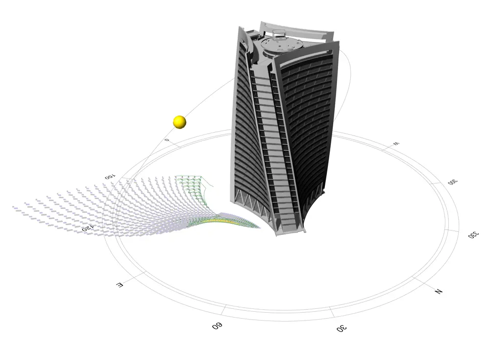
Analysis of the concentrated solar reflection from the curved glass facades of the PwC Tower © Arup
It was clear that the unusual shape of the building would lead to local concentrations of wind effects but assessing this from existing guidance was not possible, particularly the risk of deflected wind causing discomfort at ground level. Therefore, modelling was supplemented by wind tunnel tests in London. These assessed the concentration of wind loads at the edges of the facades (the corners of the triangle). The engineers addressed these by allowing a more economical sizing of the structure within the detailed design. At ground level, the tests revealed no wind problems in the sensitive areas around the entrance and lobbies, although they did identify some unexpected concentrations of wind nearby.
Construction of the building was complicated mainly because of the challenges of setting out the structure between points identified by three-dimensional coordinates rather than by conventional horizontals and verticals. Otherwise, design for buildability and close cooperation with the contractor meant that it was relatively easy to manufacture and assemble, particularly by the regularity and repetition of elements and dimensions. The core was constructed by slip-forming in a continuous concrete pour of 4,500 cubic metres over 43 days – a common practice in Europe but a novelty for office buildings in South Africa.
Richard Lawson stated that, by using clever design thinking and modern optimisation methods, the additional cost of the twist was a small premium compared with other iconic buildings. People moved into the PwC Tower earlier this year, and it is now the company’s South Africa head office.
***
This article has been adapted from "A tower with a twist", which originally appeared in the print edition of Ingenia 74 (March 2018).
Contributors
Hugh Ferguson
Author
Richard Lawson is an Associate Director in Arup’s Johannesburg office, responsible for the PwC Tower. The project team includes the client Attacq, development manager Atterbury, architect LYT Architecture, structure and facades engineer Arup, contractor WBHO, and facade fabricator Geustyn & Horak.
Keep up-to-date with Ingenia for free
SubscribeRelated content
Civil & structural

Building the Shard
The Shard is one of London's most iconic buildings. The tallest in Western Europe, it was designed by Italian architect Renzo Piano and dominates the city’s skyline. Ingenia spoke to John Parker, project director for structural engineers WSP, who outlined the engineering decisions made in building the enormous steel and glass structure.

FlexiArch
Arch bridges are strong, durable and require little maintenance. However, very few had been built since the early 1900s until the FlexiArch was developed and launched in 2007. Now, there has been a minor renaissance for this ancient form of construction.

Creating user-friendly buildings
For Michelle McDowell, a former Business Woman of the Year, a passion for joined-up design thinking and building information modelling with a user-friendly approach has enabled her to pioneer revolutionary changes in her field.

Troja Bridge
In November 2014, one of the world’s largest network arch bridges was officially opened in Prague. The UK may soon have its first network arch bridge if the go-ahead is given for a new rail project in Manchester.
Other content from Ingenia
Quick read

- Environment & sustainability
- Opinion
A young engineer’s perspective on the good, the bad and the ugly of COP27

- Environment & sustainability
- Issue 95
How do we pay for net zero technologies?
Quick read
- Transport
- Mechanical
- How I got here
Electrifying trains and STEMAZING outreach

- Civil & structural
- Environment & sustainability
- Issue 95